Er diagram tool
Содержание:
- Зачем в 1С:Предприятии понадобилась ER-модель
- Documenting an Existing Database Using Data
- Attributes
- Why use ER Diagrams?
- Common Entity Relationship Diagram Symbols
- Using ERD with BPMN Business Process Diagram (BPD)
- Cardinality
- How to Create an Entity Relationship Diagram (ERD)
- Best Practices for Developing Effective ER Diagrams
- Weak Entities
- Using ERD with Data Flow Diagram (DFD)
- Сценарий 1. Какие объекты конфигурации использует данный объект
- ER Diagrams Symbols & Notations
- WHAT IS ENTITY?
- What is an ER diagram (ERD)?
- How to Create an Entity Relationship Diagram (ERD)
- Entity Relationship Diagram Tutorial
- Сценарий 2. Разобраться с устройством механизма или подсистемы
- Conceptual, Logical and Physical data models
Зачем в 1С:Предприятии понадобилась ER-модель
Необходимость использования этой модели данных в 1С:Предприятии прямо связана с ростом платформы и значительным усложнением прикладных решений. По этой же причине мы реализовали схему данных в составе новой среды разработки EDT, которая ориентирована именно на большие конфигурации.
Если посмотреть на любую базу данных 1С:Предприятия то вы увидите, что она основана на реляционной модели. Грубо говоря, она состоит из таблиц, которые связаны между собой различными способами. Таблицы имеют поля, из этих полей формируются ключи, которые позволяют связывать таблицы друг с другом.
Такая модель удобна для компьютерной обработки, но неудобна для визуального представления разработчику. Особенно неудобна она в случае 1С:Предприятия, где большинство таблиц имеет не абстрактное, а совершенно конкретное прикладное значение.
Поэтому исторически в конфигураторе 1С:Предприятия используется другая концептуальная модель, представляющая базу данных в виде дерева объектов конфигурации. Объекты конфигурации скрывают за собой реляционную модель, они сгруппированы по принадлежности к тому или иному классу прикладных задач. Такое представление удобно для быстрого нахождения нужных объектов, изменения их свойств и т.д. Однако это представление не даёт простого и наглядного понятия о взаимной связи разных объектов между собой.
Современные прикладные решения 1С:Предприятия содержат большое количество объектов конфигурации, 10 тысяч и более. При таком количестве объектов задача нахождения их взаимных связей с помощью имеющихся инструментов становится довольно трудоёмкой. Причём трудоёмкость растёт не только за счёт прямого увеличения времени поиска ссылок среди большого количества объектов. Она растёт и косвенно, за счёт того, что найденные связи необходимо как-то запомнить и визуализировать. И если таких связей много, встаёт вопрос выбора подходящего внешнего инструмента.
Использование ER-модели (Entity-Relationship Model) как раз решает эту проблему. ER-модель представляет любую структуру данных в виде совокупности сущностей, обладающих атрибутами. Эти сущности взаимодействуют между собой при помощи связей.
В наших терминах, в терминах 1С:Предприятия, сущность это объект конфигурации, а атрибут это реквизит объекта конфигурации в широком смысле: реквизит, измерение, ресурс и т.д. Таким образом, ER-модель базы данных 1С:Предприятия это набор (никак не структурированный) объектов конфигурации (с их реквизитами), между которыми существуют некоторые связи. А схема данных это инструмент, позволяющий визуализировать эту модель.
Всё это теоретическое отступление мы написали только ради того, чтобы обратить ваше внимание на две важные вещи.
Во-первых, схема данных это не что-то опциональное, это не «бантик», добавляющий привлекательности среде разработки. Это вполне себе самостоятельный инструмент моделирования предметной области, обладающий своими преимуществами и особенностями.
Во-вторых, схема данных это не аналог и не замена дерева объектов конфигурации. Это ещё один инструмент разработки, но он, можно сказать, имеет свою собственную аудиторию.
Дерево объектов конфигурации в большей степени удобно для разработчиков, глубоко погруженных в прикладное решение, или знакомых с его генезисом. Оно позволяет быстро модифицировать приложение, при этом большую часть информации о взаимной связи объектов разработчик прекрасно знает, и обычно просто держит в голове.
В отличие от дерева объектов схема данных ориентирована скорее на тех разработчиков, которые не знакомы с прикладным решением глубоко, но которым необходимо быстро разобраться в устройстве какой-то его части. Также схема данных удобна для документирования разрабатываемых механизмов (в том числе и самими разработчиками), поскольку в понятном виде показывает связи между объектами или группами объектов.
Дальше, без общих рассуждений, мы просто хотим показать вам несколько практических сценариев использования схемы данных. Они помогут вам не только понять её назначение, но и узнать её возможности.
Documenting an Existing Database Using Data
There are two reasons to create a database diagram. You’re either designing a new schema or you need to document your existing structure.
If you have an existing database you need to to document, you create a database diagram using data directly from your database. You can export your database structure as a CSV file (there are some scripts on how to this here), then have a program generate the ERD automatically.
This will be the most accurate potrait of your database and will require no drawing on your part.
Here’s an example of a very basic database structure generated from data.
If you want to create a new plan, you can also edit the generated diagram and collaborate with your team on what changes to make.
Attributes
It is a single-valued property of either an entity-type or a relationship-type.
For example, a lecture might have attributes: time, date, duration, place, etc.
An attribute in ER Diagram examples, is represented by an Ellipse
| Types of Attributes | Description |
| Simple attribute | Simple attributes can’t be divided any further. For example, a student’s contact number. It is also called an atomic value. |
| Composite attribute | It is possible to break down composite attribute. For example, a student’s full name may be further divided into first name, second name, and last name. |
| Derived attribute | This type of attribute does not include in the physical database. However, their values are derived from other attributes present in the database. For example, age should not be stored directly. Instead, it should be derived from the DOB of that employee. |
| Multivalued attribute | Multivalued attributes can have more than one values. For example, a student can have more than one mobile number, email address, etc. |
Why use ER Diagrams?
Here, are prime reasons for using the ER Diagram
- Helps you to define terms related to entity relationship modeling
- Provide a preview of how all your tables should connect, what fields are going to be on each table
- Helps to describe entities, attributes, relationships
- ER diagrams are translatable into relational tables which allows you to build databases quickly
- ER diagrams can be used by database designers as a blueprint for implementing data in specific software applications
- The database designer gains a better understanding of the information to be contained in the database with the help of ERP diagram
- ERD Diagram allows you to communicate with the logical structure of the database to users
Common Entity Relationship Diagram Symbols
An ER diagram is a means of visualizing how the information a system produces is related. There are five main components of an ERD:
-
Entities, which are represented by rectangles. An entity is an object or concept about which you want to store information.
A weak entity is an entity that must defined by a foreign key relationship with another entity as it cannot be uniquely identified by its own attributes alone.
-
Actions, which are represented by diamond shapes, show how two entities share information in the database.
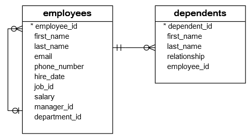
In some cases, entities can be self-linked. For example, employees can supervise other employees.
-
Attributes, which are represented by ovals. A key attribute is the unique, distinguishing characteristic of the entity. For example, an employee’s social security number might be the employee’s key attribute.
A multivalued attribute can have more than one value. For example, an employee entity can have multiple skill values.A derived attribute is based on another attribute. For example, an employee’s monthly salary is based on the employee’s annual salary.
- Connecting lines, solid lines that connect attributes to show the relationships of entities in the diagram.
-
Cardinality specifies how many instances of an entity relate to one instance of another entity. Ordinality is also closely linked to cardinality. While cardinality specifies the occurrences of a relationship, ordinality describes the relationship as either mandatory or optional. In other words, cardinality specifies the maximum number of relationships and ordinality specifies the absolute minimum number of relationships.
There are many notation styles that express cardinality.Information Engineering StyleChen StyleBachman StyleMartin Style
Using ERD with BPMN Business Process Diagram (BPD)
In business process mapping, BPMN Business Process Diagram (BPD) can be drawn to visualize business workflows. In a Business Process Diagram, there is a symbol called Data Object, which represents the data input into / output from process activities.
Since a conceptual and logical data model provides a high-level view of business objects within a system, the entities in such ERDs are aligned with data objects in BPD. You can draw ERD as a complement to BPD by representing the structure of data objects needed by a business workflow, or, on the contrary, to draw BPD in complementing an ERD by showing how the data will be utilized throughout a business process.
Cardinality
Defines the numerical attributes of the relationship between two entities or entity sets.
Different types of cardinal relationships are:
- One-to-One Relationships
- One-to-Many Relationships
- May to One Relationships
- Many-to-Many Relationships
1.One-to-one:
One entity from entity set X can be associated with at most one entity of entity set Y and vice versa.
Example: One student can register for numerous courses. However, all those courses have a single line back to that one student.
2.One-to-many:
One entity from entity set X can be associated with multiple entities of entity set Y, but an entity from entity set Y can be associated with at least one entity.
For example, one class is consisting of multiple students.
3. Many to One
More than one entity from entity set X can be associated with at most one entity of entity set Y. However, an entity from entity set Y may or may not be associated with more than one entity from entity set X.
For example, many students belong to the same class.
4. Many to Many:
One entity from X can be associated with more than one entity from Y and vice versa.
For example, Students as a group are associated with multiple faculty members, and faculty members can be associated with multiple students.
How to Create an Entity Relationship Diagram (ERD)
Now in this ERD Diagram Tutorial, we will learn how to create an ER Diagram. Following are the steps to create an ER Diagram:
Let’s study them with an Entity Relationship Diagram Example:
In a university, a Student enrolls in Courses. A student must be assigned to at least one or more Courses. Each course is taught by a single Professor. To maintain instruction quality, a Professor can deliver only one course
Step 1) Entity Identification
We have three entities
- Student
- Course
- Professor
Step 2) Relationship Identification
We have the following two relationships
- The student is assigned a course
- Professor delivers a course
Step 3) Cardinality Identification
For them problem statement we know that,
- A student can be assigned multiple courses
- A Professor can deliver only one course
Step 4) Identify Attributes
You need to study the files, forms, reports, data currently maintained by the organization to identify attributes. You can also conduct interviews with various stakeholders to identify entities. Initially, it’s important to identify the attributes without mapping them to a particular entity.
Once, you have a list of Attributes, you need to map them to the identified entities. Ensure an attribute is to be paired with exactly one entity. If you think an attribute should belong to more than one entity, use a modifier to make it unique.
Once the mapping is done, identify the primary Keys. If a unique key is not readily available, create one.
|
Entity |
Primary Key |
Attribute |
|
Student |
Student_ID |
StudentName |
|
Professor |
Employee_ID |
ProfessorName |
|
Course |
Course_ID |
CourseName |
For Course Entity, attributes could be Duration, Credits, Assignments, etc. For the sake of ease we have considered just one attribute.
Step 5) Create the ERD Diagram
A more modern representation of Entity Relationship Diagram Example
Best Practices for Developing Effective ER Diagrams
Here are some best practice or example for Developing Effective ER Diagrams.
- Eliminate any redundant entities or relationships
- You need to make sure that all your entities and relationships are properly labeled
- There may be various valid approaches to an ER diagram. You need to make sure that the ER diagram supports all the data you need to store
- You should assure that each entity only appears a single time in the ER diagram
- Name every relationship, entity, and attribute are represented on your diagram
- Never connect relationships to each other
- You should use colors to highlight important portions of the ER diagram
Weak Entities
A weak entity is a type of entity which doesn’t have its key attribute. It can be identified uniquely by considering the primary key of another entity. For that, weak entity sets need to have participation.

In above ER Diagram examples, «Trans No» is a discriminator within a group of transactions in an ATM.
Let’s learn more about a weak entity by comparing it with a Strong Entity
| Strong Entity Set | Weak Entity Set |
|---|---|
| Strong entity set always has a primary key. | It does not have enough attributes to build a primary key. |
| It is represented by a rectangle symbol. | It is represented by a double rectangle symbol. |
| It contains a Primary key represented by the underline symbol. | It contains a Partial Key which is represented by a dashed underline symbol. |
| The member of a strong entity set is called as dominant entity set. | The member of a weak entity set called as a subordinate entity set. |
| Primary Key is one of its attributes which helps to identify its member. | In a weak entity set, it is a combination of primary key and partial key of the strong entity set. |
| In the ER diagram the relationship between two strong entity set shown by using a diamond symbol. | The relationship between one strong and a weak entity set shown by using the double diamond symbol. |
| The connecting line of the strong entity set with the relationship is single. | The line connecting the weak entity set for identifying relationship is double. |
Using ERD with Data Flow Diagram (DFD)
In system analysis and design, Data Flow Diagram (DFD) can be drawn to visualize the flow of information within system processes. In a Data Flow Diagram, there is a symbol called Data Store, which represents a database table that provides the information needed by the system.
Since a physical ER Diagram provides a blueprint of an actual database, the entities in such an ERD are aligned with datastores in a DFD. You can draw ERD as a complement to DFD by representing the structure of information that flows within a system, or, on the contrary, to draw DFD in complementing an ERD by showing how the data will be utilized by the system in runtime.
Сценарий 1. Какие объекты конфигурации использует данный объект
Это самый простой сценарий. Например, у вас есть регистр Продажи. Вам нужно узнать, какие объекты конфигурации использует это регистр. То есть, на какие объекты конфигурации ссылаются его реквизиты, измерения и ресурсы.
Раньше для этого вы раскрыли бы его структуру в дереве объектов конфигурации и вручную смотрели бы типы реквизитов в палитре свойств. Если регистр большой, то, возможно, вы использовали бы команду Поиск ссылок в объекте. После этого каким-то образом вам нужно было записать то, что вы нашли.
Теперь эта задача решается значительно проще. Вы открываете редактор объекта конфигурации и переходите на закладку Схема данных. Такая закладка есть у всех прикладных объектов конфигурации.
EDT сразу же показывает вам ER-диаграмму. В неё включаются все объекты первого уровня, которые использует регистр Продажи.
На этой схеме данных видно, что регистр Продажи использует документ РасходТовара и справочники Товары и Контрагенты. Эти связи исходят из регистра. Кроме этого на схеме показаны и взаимные связи между самими используемыми объектами (между документом и справочниками).
Вообще говоря, связей может быть много. Чтобы легче ориентироваться в них вы можете выделить мышью исследуемый объект, и тогда исходящие из него связи будут подсвечены. Также будут подсвечены и реквизиты объекта, задействованные в этих связях.
Если вас интересует только одна связь, вы можете нажать на неё, и тогда будет подсвечена она и реквизит, связанный с ней.
Обычно связи обозначаются открытой стрелкой, но для некоторых связей мы используем специальные обозначения: закрытая стрелка и ромб. Например, другая схема данных может выглядеть так:
Закрытой стрелкой обозначается связь с владельцем, а ромбом – с регистратором. Это помогает визуально отличать «техногенные» связи от прикладных.
Такую схему данных, которая открывается на закладке редактора объекта конфигурации, вы можете изменять и модифицировать: раскрывать группы реквизитов, перетаскивать объекты, располагая их более удобным образом, и т.д.
Но нужно учитывать, что эти изменения не сохраняются в конфигурации. Ту схему, которую вы видите, вы можете сохранить как картинку или напечатать (всю схему, или только её часть). Но в следующий раз, когда вы откроете редактор объекта конфигурации и перейдёте на закладку Схема данных, схема будет нарисована заново в стандартном виде.
Поэтому здесь, в этом месте, не нужно увлекаться наведением «красоты», для этого есть другой сценарий, который мы тоже рассмотрим далее.
ER Diagrams Symbols & Notations
Entity Relationship Diagram Symbols & Notations mainly contains three basic symbols which are rectangle, oval and diamond to represent relationships between elements, entities and attributes. There are some sub-elements which are based on main elements in ERD Diagram. ER Diagram is a visual representation of data that describes how data is related to each other using different ERD Symbols and Notations.
Following are the main components and its symbols in ER Diagrams:
- Rectangles: This Entity Relationship Diagram symbol represents entity types
- Ellipses : Symbol represent attributes
- Diamonds: This symbol represents relationship types
- Lines: It links attributes to entity types and entity types with other relationship types
- Primary key: attributes are underlined
- Double Ellipses: Represent multi-valued attributes
WHAT IS ENTITY?
A real-world thing either living or non-living that is easily recognizable and nonrecognizable. It is anything in the enterprise that is to be represented in our database. It may be a physical thing or simply a fact about the enterprise or an event that happens in the real world.
An entity can be place, person, object, event or a concept, which stores data in the database. The characteristics of entities are must have an attribute, and a unique key. Every entity is made up of some ‘attributes’ which represent that entity.
Examples of entities:
- Person: Employee, Student, Patient
- Place: Store, Building
- Object: Machine, product, and Car
- Event: Sale, Registration, Renewal
- Concept: Account, Course
Notation of an Entity
Entity set:
Student
An entity set is a group of similar kind of entities. It may contain entities with attribute sharing similar values. Entities are represented by their properties, which also called attributes. All attributes have their separate values. For example, a student entity may have a name, age, class, as attributes.
Example of Entities:
A university may have some departments. All these departments employ various lecturers and offer several programs.
Some courses make up each program. Students register in a particular program and enroll in various courses. A lecturer from the specific department takes each course, and each lecturer teaches a various group of students.
What is an ER diagram (ERD)?
First of all, what is an Entity Relationship Diagram?
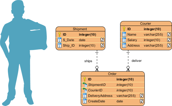
Entity Relationship Diagram, also known as ERD, ER Diagram or ER model, is a type of structural diagram for use in database design. An ERD contains different symbols and connectors that visualize two important information: The major entities within the system scope, and the inter-relationships among these entities.
And that’s why it’s called «Entity» «Relationship» diagram (ERD)!
When we talk about entities in ERD, very often we are referring to business objects such as people/roles (e.g. Student), tangible business objects (e.g. Product), intangible business objects (e.g. Log), etc. «Relationship» is about how these entities relate to each other within the system.
How to Create an Entity Relationship Diagram (ERD)
Now in this ERD Diagram Tutorial, we will learn how to create an ER Diagram. Following are the steps to create an ER Diagram:
Let’s study them with an Entity Relationship Diagram Example:
In a university, a Student enrolls in Courses. A student must be assigned to at least one or more Courses. Each course is taught by a single Professor. To maintain instruction quality, a Professor can deliver only one course
Step 1) Entity Identification
We have three entities
- Student
- Course
- Professor
Step 2) Relationship Identification
We have the following two relationships
- The student is assigned a course
- Professor delivers a course
Step 3) Cardinality Identification
For them problem statement we know that,
- A student can be assigned multiple courses
- A Professor can deliver only one course
Step 4) Identify Attributes
You need to study the files, forms, reports, data currently maintained by the organization to identify attributes. You can also conduct interviews with various stakeholders to identify entities. Initially, it’s important to identify the attributes without mapping them to a particular entity.
Once, you have a list of Attributes, you need to map them to the identified entities. Ensure an attribute is to be paired with exactly one entity. If you think an attribute should belong to more than one entity, use a modifier to make it unique.
Once the mapping is done, identify the primary Keys. If a unique key is not readily available, create one.
|
Entity |
Primary Key |
Attribute |
|
Student |
Student_ID |
StudentName |
|
Professor |
Employee_ID |
ProfessorName |
|
Course |
Course_ID |
CourseName |
For Course Entity, attributes could be Duration, Credits, Assignments, etc. For the sake of ease we have considered just one attribute.
Step 5) Create the ERD Diagram
Entity Relationship Diagram Tutorial
Here are some best practice tips for constructing an ERD:
- Identify the entities. The first step in making an ERD is to identify all of the entities you will use. An entity is nothing more than a rectangle with a description of something that your system stores information about. This could be a customer, a manager, an invoice, a schedule, etc. Draw a rectangle for each entity you can think of on your page. Keep them spaced out a bit.
- Identify relationships. Look at two entities, are they related? If so draw a solid line connecting the two entities.
- Describe the relationship. How are the entities related? Draw an action diamond between the two entities on the line you just added. In the diamond write a brief description of how they are related.
- Add attributes. Any key attributes of entities should be added using oval-shaped symbols.
- Complete the diagram. Continue to connect the entities with lines, and adding diamonds to describe each relationship until all relationships have been described. Each of your entities may not have any relationships, some may have multiple relationships. That is okay.
Сценарий 2. Разобраться с устройством механизма или подсистемы
Второй сценарий заключается в том, что вам нужно разобраться с устройством незнакомого механизма или подсистемы. Например, нужно понять, как устроена подсистема ТоварныеЗапасы. Какие объекты в ней задействованы и как они связаны друг с другом.
В этом случае, как и в первом сценарии, вы можете открыть редактор этой подсистемы и перейти на закладку Схема данных. Здесь вы увидите более интересную картину, потому что кроме объектов на этой схеме будут показаны и подчинённые подсистемы.
Подсистемы являются группами объектов. Содержащиеся в них объекты имеют связи с объектами, которые находятся «снаружи». Чтобы посмотреть, как устроена любая из этих подсистем, например подсистема Характеристики, вы можете кликнуть на ней прямо в схеме, и увидите её устройство.
Интересным моментом является то, что схема данных поддерживает переходы Вперед / Назад по аналогии с браузерами. Поэтому, разобравшись с устройством этой подчинённой подсистемы, вы можете просто нажать кнопку Назад, и вернуться к предыдущей схеме.
Conceptual, Logical and Physical data models
An ER model is typically drawn at up to three levels of abstraction:
While all the three levels of an ER model contain entities with attributes and relationships, they differ in the purposes they are created for and the audiences they are meant to target.
A general understanding to the three data models is that business analyst uses a conceptual and logical model to model the business objects exist in the system, while database designer or database engineer elaborates the conceptual and logical ER model to produce the physical model that presents the physical database structure ready for database creation. The table below shows the difference between the three data models.
Conceptual model vs Logical model vs Data model:
| ERD features | Conceptual | Logical | Physical |
|---|---|---|---|
| Entity (Name) | Yes | Yes | Yes |
| Relationship | Yes | Yes | Yes |
| Columns | Yes | Yes | |
| Column’s Types | Optional | Yes | |
| Primary Key | Yes | ||
| Foreign Key | Yes |
Conceptual data model
Conceptual ERD models the business objects that should exist in a system and the relationships between them. A conceptual model is developed to present an overall picture of the system by recognizing the business objects involved. It defines what entities exist, NOT which tables. For example, ‘many to many’ tables may exist in a logical or physical data model but they are just shown as a relationship with no cardinality under the conceptual data model.
Conceptual data model example
NOTE: Conceptual ERD supports the use of generalization in modeling the ‘a kind of’ relationship between two entities, for instance, Triangle, is a kind of Shape. The usage is like generalization in UML. Notice that only conceptual ERD supports generalization.
Logical data model
Logical ERD is a detailed version of a Conceptual ERD. A logical ER model is developed to enrich a conceptual model by defining explicitly the columns in each entity and introducing operational and transactional entities. Although a logical data model is still independent of the actual database system in which the database will be created, you can still take that into consideration if it affects the design.
Logical data model example
Physical data model
Physical ERD represents the actual design blueprint of a relational database. A physical data model elaborates on the logical data model by assigning each column with type, length, nullable, etc. Since a physical ERD represents how data should be structured and related in a specific DBMS it is important to consider the convention and restriction of the actual database system in which the database will be created. Make sure the column types are supported by the DBMS and reserved words are not used in naming entities and columns.
